rpp - Raspberry Pi PIC Programmer using GPIO
Introduction
Microchip PIC® 8-bit microcontrollers are quite popular amongst hobbyists,
and I've used them for a long time in several of my projects. They are very cheap,
use only 35 assembly instructions that are easy to learn, and most importantly
they use flash memory, which gives you the possibility to program the device
virtually as many times as you want during your experiments.
Up until now I've used a simple serial interface and
picprog
to program them under Linux, but sadly the trend is not to include a serial
port anymore on new computers/laptops. Of course there are USB programmers
on the market, but quite often their price exceeds 30€ and not all of them work
well on Linux. Also a commercial programmer usually supports hundreds of different
chips, while all I needed was a simple and cheap way to program, say, the four chips
I work with most of the time. So, with the introduction of the
Raspberry Pi, and the possibility to
control external hardware through its GPIO
connector, I thought it would be worth spending some time to design a simple interface and write a
software to program some PICs. The result of about a week of work is rpp - a
Raspberry Pi PIC Programmer that uses the GPIO connector.
These are the basic operations you can perform with rpp:
- Bulk erase the chip
- Read the chip and save its memories content to a Intel HEX 16-bit file
- Write a program to the chip. The location to be written are read from a Intel HEX 16-bit file
At the moment this program supports only 11 different devices (basically the ones I had here and could test) but I plan to add support for other devices in the future
License
rpp is free software and it is released under the GNU GPLv3 license.
Hardware
PICs are programmed using a serial method. You need a VPP of 12V to 14V to enter
in Programming/Verify mode, and then the communication is done serially using a CLOCK
line and a DATA line (which is bidirectional). The hardware interface is purposely
simple (and as a consequence, cheap) and uses only 14 resistors, 2 capacitors and 6 bjts,
plus a voltage regulator to derive the 5V from the 12V supply. Since the average
current required to program a PIC is low, you can use a 78L05 instead of a standard 7805.
In fact I tested the programmer with the 78L05 and it didn't even get warm during programming.
Here's a schematic of the interface (click on the images to enlarge):
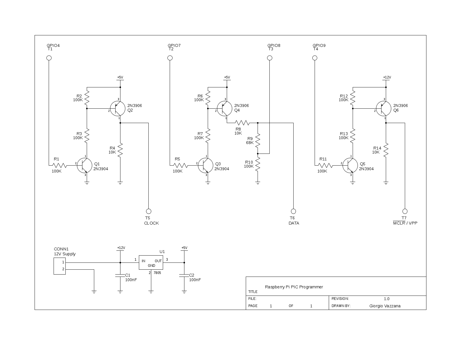
The terminals on the top of the schematic, labeled T1-T4, go to the Raspberry Pi GPIO connector.
Of course you also need to connect the ground of the Raspberry Pi (pin P1-06 on the GPIO connector)
to the ground of the programmer. If you want to use different GPIO pins on the Raspberry Pi, all
you need to do is modify the defines at the beginning of the source file (rpp.c).
The terminals labeled T5-T7 are the signals that go to the PIC microcontroller for serial
programming (CLOCK, DATA, and VPP programming voltage), and again, you need to connect 5V and
ground to the PIC too.
For those of you interested, this is how it works: the stage composed by the npn and pnp transistors
(Q1 and Q2) acts as a level shifter (since the GPIO connector of the Raspberry Pi works at 3.3V) and
at the same time avoids drawing too much current from the GPIO pins. A high level on T1 (GPIO4) makes
Q1 go into saturation (easy to see: assuming a VCEsat of 0.1V, we have Ic = 42uA, and Ib = 26uA >>
(Ic/β)), effectively connecting to ground the lower terminal of R3, given that VCEsat is less than
100mV typically. This turns on Q2 and pulls T5 (CLOCK) high. When a low level is present on T1,
both transistors are off, and T5 is pulled down by R4. The resistor R2 make the transistor Q2
turn off faster (otherwise, the charge stored in the base of Q2 has nowhere to go when Q1 goes
from on to off, and this results in a longer storage time. This problem is not present on Q1
since the GPIO pins can sink current).
The stage composed by Q3/Q4 works pretty much in the same way. When T2 (GPIO7) is high both
transistors are on, and we have VDD*((R9+R10)/(R8+R9+R10)) = 4.7V on T6 (DATA), neglecting VCEsat.
When they are off, again T6 is pulled low by (R9+R10). When DATA becomes an output on the PIC,
we switch Q3 and Q4 off in software (effectively disconnecting R8), and we use the voltage divider
made up by R9 and R10 to transform 0/5V voltage levels in 0/3V (the divider's voltage ratio is
R10/(R9+R10)=0.6, VDD*0.6=3V) before feeding this signal to the GPIO.
Lastly, Q5/Q6 pull T7 (VPP) to 12V when on, making the PIC enter Program/Verify mode.
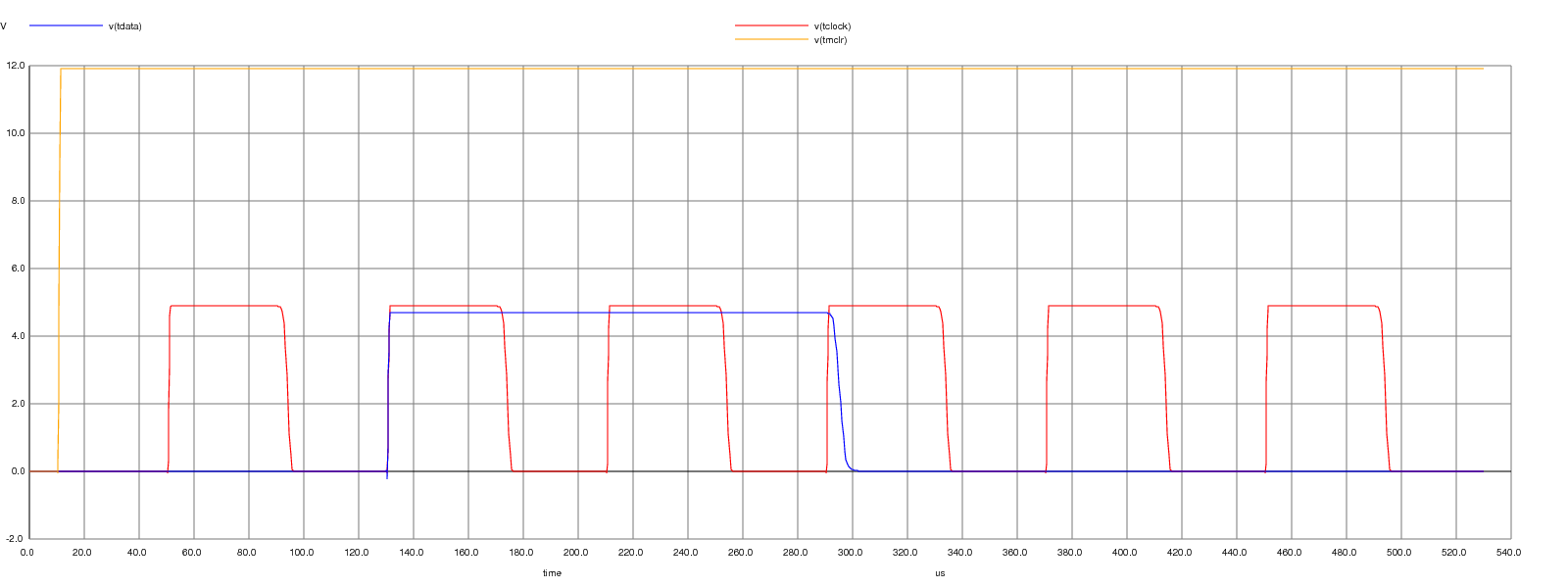
Despite the working of this interface being pretty simple, I have ran a simulation on it using
ngspice. You can download the source file
here. To launch the simulation run:
$ ngspice rpp-interface.net
The output shows the PIC entering in Program/Verify mode (holding CLOCK and DATA low while VPP is
raised), and then a 'Increment Address' command is sent (0x06, 6 bit, lsb first; DATA is latched
on falling edges of the CLOCK):
Note 1: this interface does not support In-Circuit Serial Programming (ICSP) at the moment, but I
plan to work on one that does.
Note 2: someone on
hackaday suggested the use of a SN74LVC245A octal transceiver for simplyfing
the interface. After looking at the datasheet I don't think that could work, because when programming
the PIC, CLOCK and DATA have Schmitt Trigger inputs, and they need a minimum input high level of
0.8*VDD, that is 4V. If you operate the 74LVC245 at 3.3V, the VOH of this transceiver (3.3V at best)
isn’t enough to be recognized as a valid high level from the PIC.
About the 78L05 regulator: it was added because I didn’t want to draw any current from the RPi,
apart from that needed to drive the bases of the switching transistors. Think of it as an additional
"protection" for the Raspberry Pi: if they chip you're programming is faulty or shorted, the worst it
can happen is that the regulator will activate its thermal or short circuit protection, saving the RPi.
I agree that it's possible to build an interface with a lower number of parts, but as it is now its
cost is probably under 2€, you can use any type of equivalent npn/pnp pair (like bc547/bc557) and
it’s something a beginner could solder easily as a first project.
How to compile rpp
rpp is written in C an does not use any external library. In order to compile rpp you need:
- gcc
- make
If you're using Raspbian, all the dependencies are already installed, so you can
compile the source file simply with:
$ make
If you want to clean the build directory just run:
$ make clean
The resulting binary can be put, for example, in /usr/local/bin or can be run
from the local directory.
Using rpp
You can access the help by running:
$ ./rpp -h
Raspberry Pi PIC Programmer, v0.1

Usage: rpp [options]
       -h          print help
       -D          turn debug on
       -i file     input file
       -o file     output file (ofile.hex)
       -r          read chip
       -w          bulk erase and write chip
       -e          bulk erase chip
       -s          skip all-ones memory locations

Supported PICs: pic16f84a, pic16f627a, pic16f628a, pic16f648a, pic16f870, pic16f871, pic16f872, pic16f873, pic16f874, pic16f876, pic16f877
If you simply run rpp with no arguments it tries to autodetect the PIC connected to the
programmer, by reading the device ID of the PIC (the device ID is the word located at address
0x2006 in the configuration memory). If you get an error here, either you are using one of the
unsupported chips, or there is something wrong in the programmer and/or the connection to the
Raspberry Pi.
Note: every operation has to be performed as root, in order to be able to access to the GPIO
registers of the Raspberry Pi SoC.
$ sudo ./rpp
Raspberry Pi PIC Programmer, v0.1

device_id = 0x1068
pic16f628a detected, revision 0x08
If you want to write a program to the PIC you need to specify the -w option, and give it an input file (in Intel HEX 16-bit format) that contains the program:
$ sudo ./rpp -w -i clock.hex
Raspberry Pi PIC Programmer, v0.1

device_id = 0x1068
pic16f628a detected, revision 0x08
Reading hex file...
Bulk erasing chip...
Writing chip...
Reading the data inside the PIC is just as simple: use the -r option, and specify a name for the output file:
$ sudo ./rpp -r -o outfile.hex
Raspberry Pi PIC Programmer, v0.1

device_id = 0x1068
pic16f628a detected, revision 0x08
Reading chip...
Writing hex file...
The program options have the following meaning:
- -h: print the help text
- -D: turn debug mode on. When using this option rpp will show you lots of informations about the memory locations being read or written, or informations about the parsing of the HEX file. Useful in case of errors, to show what the program was doing and why it failed
- -i file: specify an input file for the program to be written to the PIC. You must specify this option when writing to a chip (-w), otherwise you'll get an error. The input file must be in Intel HEX 16-bit format. Several assemblers are able to produce such files, such as gpasm
- -o file: specify the output file when reading data from a PIC. If you do not use this option, the default output file (ofile.hex) will be used
- -r: read the PIC and save the content of its program memory, configuration memory (user ID locations and configuration word), and data memory to a Intel HEX 16-bit file. If you want to specify an output file name different from the default use the -o option
- -w: write a program to the PIC. An input file must be specified with the -i option. The chip is bulk erased first, and then only the memory locations present in the HEX file are written to the PIC. Every memory location is read after being written, and if the two values are different an error is reported. If user ID locations (addresses from 0x2000 to 0x2003), configuration word (address 0x2007) and eeprom data (addresses starting at 0x2100) are present in the HEX file they are programmed too
- -e: bulk erase the chip. Both program memory and data memory are erased and filled with all-ones words (0x3FFF for 14-bit program memory, and 0xFF for 8-bit data memory). The user ID locations and configuration word may or may not be erased depending on the chip
- -s: skip all-ones memory locations. This option is used only when reading the chip. When present, all program memory locations with value 0x3FFF, all user ID locations with value 0x3FFF and all data memory locations with value 0xFF will be discarded and will not be written to the output HEX file. Configuration word will always be written regardless of its value
Complete example
Let's make a led blink at exactly 1 Hz using a pic16f628a! Copy this program and save it to a file called led.asm:
; Simple program to make a led (connected to RA0, pin 17) blink at 1 Hz
; It uses the internal 4MHz oscillator, so no external crystal is required

		processor	16F628A
		radix		dec
		include		p16f628a.inc
		errorlevel	-302
		__config	_CP_OFF & _DATA_CP_OFF & _LVP_OFF & _BOREN_OFF & _MCLRE_ON & _PWRTE_ON & _WDT_OFF & _INTOSC_OSC_CLKOUT


; constants
led		equ	0

; User ID Locations
		org	H'2000'
		dw	H'3F80'
		dw	H'3F81'
		dw	H'3F82'
		dw	H'3F83'

; EEPROM data
		org	H'2100'
		de	"Programmed with rpp"

; variables in ram
		org	H'20'
i		res	1
j		res	1

; reset vector
		org	H'00'
		goto	setup

; interrupt vector
		org	H'04'


setup		clrf	PORTA
		movlw	H'07'		;Turn comparators off and enable
		movwf	CMCON		;pins for I/O functions
		bsf	STATUS, RP0
		movlw	B'00011110'
		movwf	TRISA
		movlw	B'11111111'
		movwf	TRISB
		bcf	STATUS, RP0

start		bcf	PORTA, led
		movlw	234		;180183us
		call	delay
		movlw	234		;180183us
		call	delay
		movlw	181		;139373us -> total = 499739us
		call	delay
		bsf	PORTA, led
		movlw	234
		call	delay
		movlw	234
		call	delay
		movlw	181
		call	delay
		goto	start

; -----------------delay-----------------------------------
; Software delay variable with w
; Data:      w
; Variables: i, j

delay		movwf	i		;1 us
		clrf	j		;1 us

dloop		decfsz	j, F		;(j-1) x 1 us + 2 us	(j==0 -> j=256)
		goto	dloop		;(j-1) x 2 us

		decfsz	i, F		;(i-1) x 1 us + 2 us
		goto	dloop		;(i-1) x 2 us

		return			;2 us

; cycles =     (3j-1)*i + (3i-1) + 4
; j=256 ->  (3*256-1)*i + (3i-1) + 4
; total  = 770*i + 3


		end
The Eeprom data is not used in this simple example, but I've added it to show you
that the programmer will indeed write those locations to the data memory. Assemble
the program using gpasm:
gpasm -a inhx16 led.asm
This will produce the following output file (led.hex)
:010000002804D3
:0400040001853007009F168303
:08000800301E008530FF00861283100530EA201C68
:0800100030EA201C30B5201C140530EA201C30EAE8
:08001800201C30B5201C280D00A001A10BA1281E1A
:030020000BA0281E0008E4
:042000003F803F813F823F83DA
:012007003F3168
:0821000000500072006F006700720061006D006D92
:08210800006500640020007700690074006800200A
:032110000072007000707A
:00000001FF
You're now ready to write the program to the PIC:
$ sudo ./rpp -w -i led.hex
Done! Use a breadboard to connect 5V and ground to the PIC, connect pin 4 (MCLR negated)
to VDD through a 10K resistor, and then connect RA0 of the PIC to a 1K resistor in
series with a led with the cathode to ground and you should see it blink!
Supported chips
- pic16f84a
- pic16f627a, pic16f628a, pic16f648a
- pic16f870, pic16f871, pic16f872, pic16f873, pic16f874, pic16f876, pic16f877
Tested chips
- pic16f84a
- pic16f628a
- pic16f876
Pictures
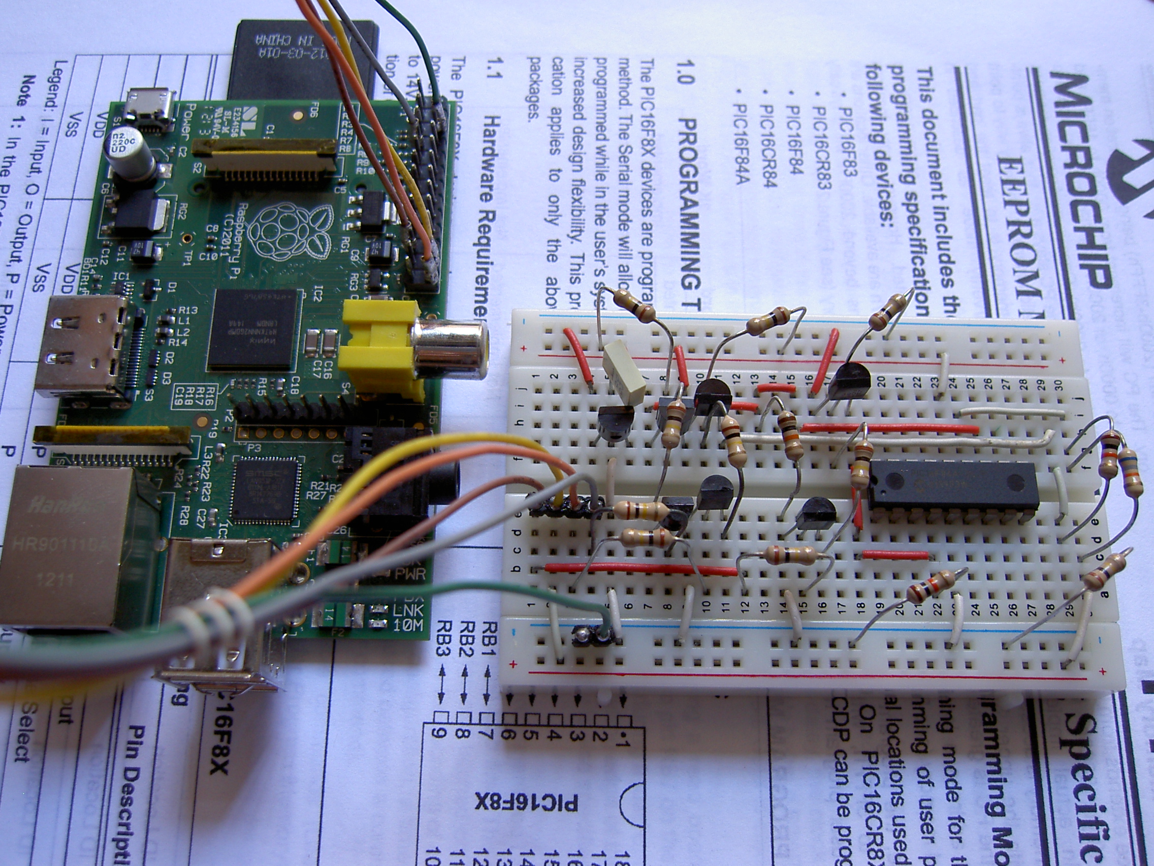
This is a picture of the hardware interface that I've built on a breadboard:

Interface next to the Raspberry Pi:
Code
You can look at the latest version of the source code (in html format, with pretty syntax highlighting) here: rpp.c
Download
The following versions of rpp are available for download. Please note that rpp is still in development and it should be considered beta software. We recommend you to download the latest version.
- 584685506b1af49f5ba05fae2bef1814 rpp010.tgz (Tue, 14 Aug 2012)
External Documentation
To develop the software I used the good documentation ("EEPROM Memory Programming Specification") present at the Microchip website. In particular, I have read the following documents so far:
- PIC16F8X EEPROM Memory Programming Specification
- PIC16F627A/628A/648A EEPROM Memory Programming Specification
- PIC16F87X EEPROM Memory Programming Specification
Also, wikipedia has a good page about the Intel HEX format.
Algorithm / Speed
There are two algorithms that can be used when programming a PIC: the first one doesn't
need a bulk erase before writing the chip, and uses a sequence of "Load Data - Begin
Erase/Programming Cycle" commands. Of course in this way only the memory locations specified
in the HEX file are written, and all the others maintain their old value.
The second algorithm involves a bulk erase first, and then a series of "Load Data - Begin
Programming Only Cycle" commands. This method has the advantage to be faster ("Begin
Programming Only Cycle" are typically twice as fast as "Begin Erase/Programming Cycle")
and also cleans the PIC memories. Plus, it is the only method supported by newer PICs, like
the pic16f628a. For this reason rpp supports only the second algorithm.
The required signals for serial programming are obtained by bit-banging the GPIO pins of the
Raspberry Pi. I have inserted a delay to make sure that everything work as intended, and currently
this delay is set to 40us. This gives us a period of 2*40us and a clock frequency of 12.5kHz.
With these settings reading a 1K words device (like the pic16f84a) takes 7.7 seconds. If you
want you can lower this delay (it's the '#define DELAY 40' in the source code) to have faster
read/write times. You should be able to go at least as down as 10us.
Forum / Contacs
I've opened a thread about rpp on the Raspberry Pi forum. You can post a message there for the time being if you have questions/suggestions or want to report a bug. Or, you can look at the home page of this site for my contact informations.
TODO
- Add support for more devices
- Implement a 'verify' mode after writing the chip (actually that would be a second verification, the software already checks every memory cell written and reports an error in case of mismatch)
- Implement the possibility to remove code protection
- Design a ICSP-compatible interface
Changelog
version 0.10:

	* Initial release with support for 11 devices